

 Eng
Eng 
 русский
 Español

 Home / News / Industry News / how does a dc motor work: Applications, Selection Criteria, and Practical Guidance
 how does a dc motor work: Applications, Selection Criteria, and Practical Guidance
 2026.09.23
 Industry News
From the fan cooling your desk to the drill spinning in a workshop, small electric machines quietly do work all around us, and most of them share the same beating heart: a DC motor. As a manufacturer of micro DC motors since 1988, we have spent more than three decades building these compact components for household appliances, power tools, automotive parts, and industrial equipment. In this guide, we explain how a DC motor works in plain language, with the practical insight that comes from producing millions of units every year.
What Is a DC Motor?
A DC motor is a device that converts direct current electrical energy into mechanical rotation. The physics behind it goes back nearly two hundred years: when electric current flows through a conductor placed inside a magnetic field, a force acts on that conductor. Wind the conductor into a coil, mount it on a shaft, and the force becomes spinning motion. What makes DC motors so widely used is their straightforward behavior. Apply power and the shaft rotates; reverse the polarity and it rotates the other way; adjust the voltage and the speed follows. That simplicity and controllability explain why micro DC motors, from compact 300-series frames to larger 900-series designs, remain the default choice for small devices.
The Main Parts of a DC Motor
Understanding the working process is much easier once you know the components that make rotation possible:
- Stator: the stationary part of the motor, usually built with permanent magnets in micro DC motors, which provides a constant magnetic field.
- Rotor (armature): the rotating part, made of wire windings wrapped around a laminated iron core and fixed to the output shaft.
- Commutator: a segmented copper sleeve on the rotor shaft that reverses the current direction in the windings as the rotor turns.
- Brushes: spring-loaded carbon contacts that press against the commutator and carry current from the power supply into the spinning rotor.
- Shaft and bearings: the parts that transmit torque to the load and keep rotation smooth and stable.
In small brushed motors, the stator is normally made of permanent magnets rather than wound field coils, which keeps the motor light, efficient, and cost-effective. Our RS390 motor for vacuum cleaners is a typical example of this permanent-magnet construction, delivering strong suction performance in a compact frame.
How Does a DC Motor Work? Step by Step
With the components clear, let us follow the current through a running motor:
- Current enters the windings. The power supply pushes direct current through the brushes, onto the commutator, and into the coil windings on the rotor.
- Magnetic fields interact. The energized coil sits inside the stator's magnetic field, and the interaction produces a force on each side of the coil in opposite directions.
- Torque is created. Because these opposing forces act on either side of the shaft, they generate a twisting force, known as torque, that starts the rotor turning.
- The commutator switches the current. As the rotor spins, the commutator segments pass the brushes and reverse the current direction in the coil every half revolution.
- Rotation becomes continuous. Since the current is switched at exactly the right moment, the magnetic force keeps pushing the rotor in the same direction, and the shaft spins steadily for as long as power is applied.
The Force Behind the Motion
A simple way to picture the effect is to imagine two magnets facing each other with a current-carrying wire between them. The wire is pushed by the interaction between its own magnetic field and the field of the magnets, and the direction of that push follows a rule known as Fleming's left-hand rule. In a motor, this push acts on every turn of the armature winding at once, and the combined result is smooth, usable torque at the shaft.
Why the Commutator Matters
Without commutation, the coil would simply rotate until its own magnetic field lined up with the stator's field and then stop. The commutator works as a mechanical switch, flipping the current direction just as the rotor passes the halfway point. That constant flipping keeps one side of the coil always being pushed forward, which is what turns a brief kick of force into continuous rotation.
What Controls Speed and Torque?
In practice, a few key variables determine how a DC motor behaves inside your device. Voltage sets the baseline speed: raise it and the motor spins faster, lower it and the motor slows down. Current reflects the workload: the harder the motor works, the more current it draws, and that current translates directly into output torque. Mechanical design, including the magnetic circuit and any gearing, then shapes how speed and torque are finally balanced at the shaft.
| Factor | Effect on the Motor | Typical Example |
|---|---|---|
| Applied voltage | Speed rises and falls roughly in proportion to voltage | Adjusting fan speed settings |
| Current draw | Higher load demands more current, producing more torque | A drill working through hardwood |
| Magnetic field strength | A stronger field yields more torque per ampere | High-performance permanent magnets |
| Gear reduction | Trades rotational speed for higher output torque | Electric screwdrivers and locks |
When an application needs high torque at low speed, a gearbox is usually added to the motor. Gear motors pair a DC motor with a reduction gear train, trading rotational speed for output torque, which is exactly what an electric screwdriver needs to drive a screw firmly without stalling.
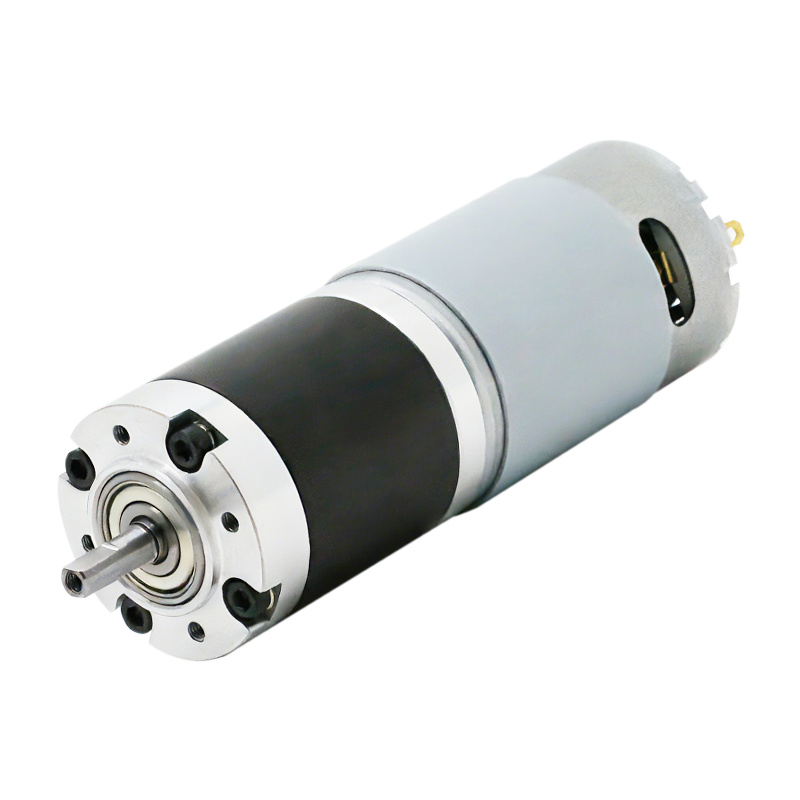 Custom Small Gear Motor ManufacturersHongyang offers customized solutions for gearboxes and gear motors, covering output shaft position, reduction ratio, motor speed, motor torque, and other parameters. T...View Product →
Brushed vs. Brushless: Two Ways to Build a DC Motor
Everything described so far applies to the classic brushed DC motor, where brushes and a commutator handle the switching mechanically. A brushless DC motor takes a different approach: the windings sit on the stator, permanent magnets sit on the rotor, and an electronic controller switches the current between phases. Removing the wearing parts gives brushless designs a longer service life, higher efficiency, and quieter operation, which is why drones and precision equipment increasingly favor them. The trade-off is that a brushless motor cannot simply be wired to a battery; it needs a driver circuit to run.
| Feature | Brushed DC Motor | Brushless DC Motor |
|---|---|---|
| Commutation | Mechanical, via brushes and commutator | Electronic, via controller |
| Lifespan | Limited by brush wear | Longer, with no brush contact |
| Efficiency | Moderate | Higher |
| Noise and EMI | Higher | Lower |
| Cost and complexity | Simple and economical | Requires a driver circuit |
In the industry, this shift is easy to observe. As we discussed in our article on why brushed DC motors are gradually being replaced, both technologies still have their place, and the right choice depends on cost targets, lifetime expectations, and control requirements. For lightweight, high-speed flight platforms in particular, brushless designs are hard to beat.
Where DC Motors Are Used Every Day
Once you understand the working principle, you start noticing DC motors everywhere. In the home, they drive vacuum cleaners, coffee machines, hair dryers, electric fans, and motorized curtains. In the office, they power paper shredders, printers, and electric pencil sharpeners. Outdoors, they run lawnmowers, hedge trimmers, and leaf blowers, while in vehicles they lift windows, lock doors, and adjust seats. On the factory floor, they move robotic arms, sort parcels, and dispense products from vending machines. We have gathered these use cases across our application pages, where you can see how different motor sizes and specifications are matched to different devices.
Choosing the Right DC Motor for Your Product
For engineers and buyers, understanding how a DC motor works is the first step toward selecting the right one. Start by defining your supply voltage, required torque and speed, allowable size, noise limits, and expected lifetime, then match those requirements to a suitable motor family. Since 1988, we have grown from the first micromotor factory in Yuyao into a manufacturer with more than 10 production lines and an annual capacity exceeding 10 million units, offering brushed DC motors from the 300 to the 900 series, brushless motors, and gear motors, all produced under ISO 9001 certified quality management and compliant with RoHS and REACH standards. If you are developing a product that needs compact rotational power, our engineering team is glad to help you select or customize the right motor, and you can request a free quote at any time.
News
-
Brush DC Motor Origins and Physical Foundations The Brush DC Motor is a pioneer in converting electrical energy into mechanical motion, and its history is closely intertwined with ...
READ MORE -
Who Is Still Using Brushed DC Motors These Days? Brushed DC motors in small appliances Despite the growing adoption of brushless motor technology, small appliances remain a major c...
READ MORE -
Brush DC Motor Applications in Consumer Electronics and Smart Devices Brush DC Motor Role in Consumer Electronics Design Brush DC Motor plays a critical role in the design and func...
READ MORE

Quick Links
 Home
Home


Copyright © Yuyao Hongyang Micromotor Co., Ltd. All rights reserved.

