

 Eng
Eng 
 русский
 Español


Small Gear Motor: Types, Selection & Applications Guide
 2026.06.24
 Industry News
What Is a Small Gear Motor?
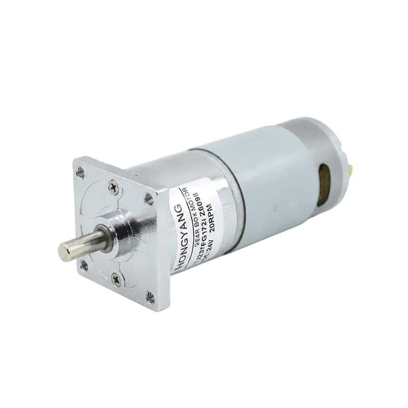
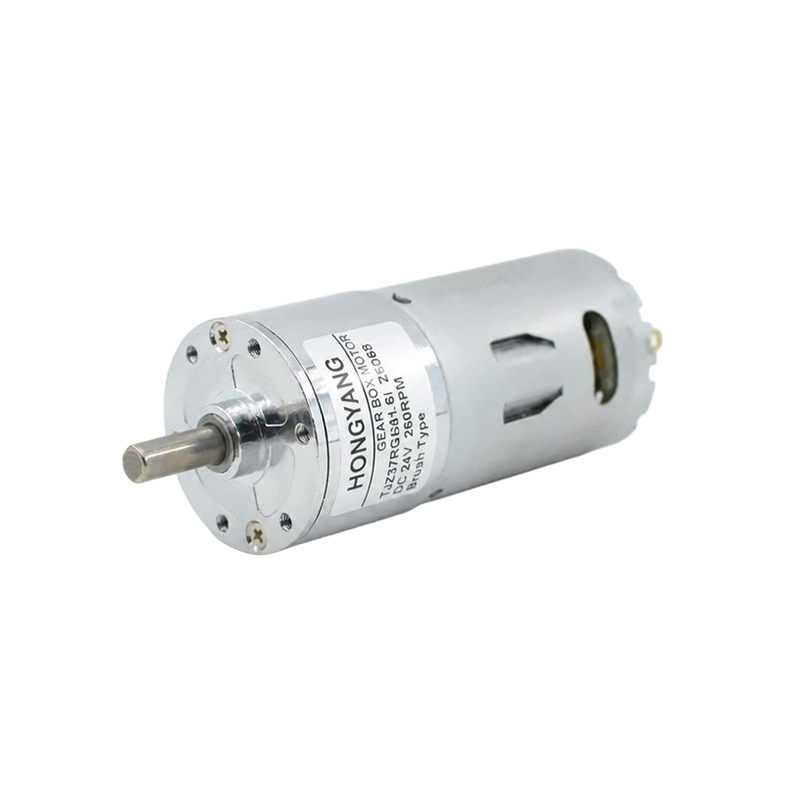
A small gear motor is a compact, self-contained unit that integrates an electric motor with a reduction gearbox, delivering high torque at low speed in a minimal footprint. Unlike using a motor and gearbox as separate components, a small gear motor combines both into a single assembly—reducing installation space, simplifying wiring, and eliminating shaft alignment issues. These units typically produce output torques from 0.01 N·m to 500 N·m and operate at output speeds from 1 RPM to 600 RPM, making them indispensable in automation, robotics, medical devices, and consumer electronics.
The defining characteristic is the gear reduction stage, which multiplies torque while proportionally reducing speed. A motor spinning at 3,000 RPM paired with a 100:1 gearbox delivers an output of 30 RPM with approximately 100 times the torque (minus efficiency losses). This fundamental trade-off is what makes small gear motors so versatile across industries.
Types of Small Gear Motors and How They Differ
Not all small gear motors are built alike. The gear mechanism inside determines torque capacity, backdrivability, noise level, and efficiency. Choosing the wrong type is one of the most common and costly design mistakes.
Spur Gear Motor
Spur gear motors use straight-cut teeth on parallel shafts. They are the simplest and most cost-effective design, achieving efficiencies of 95–98% per stage. Their main drawback is noise—tooth engagement creates a characteristic whine at higher speeds. Best suited for low-speed, moderate-torque applications such as conveyor drives, vending machines, and toy mechanisms.
Planetary Gear Motor
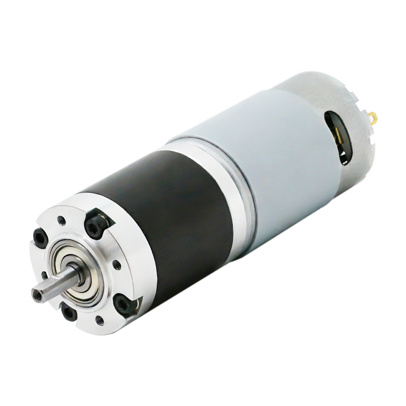
Planetary gear motors distribute load across three or more planet gears surrounding a central sun gear. This coaxial arrangement delivers high torque density—often 3–5 times the torque of an equivalent spur gear motor of the same diameter—and superior concentricity. Single-stage efficiency is typically 90–97%. They are the preferred choice for robotics joints, power tools, and precision actuators where a high torque-to-size ratio is critical.
Worm Gear Motor
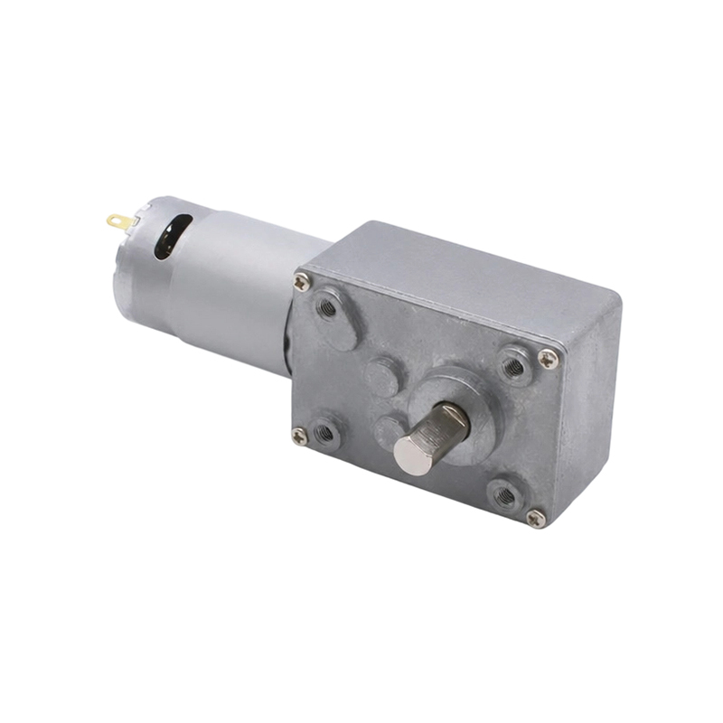
A worm gear motor uses a helical worm screw meshing with a worm wheel at a 90° angle, enabling very high single-stage reduction ratios of 5:1 to 100:1. The key advantage is self-locking: at ratios above approximately 20:1, the output shaft cannot back-drive the motor, making them ideal for lifts, gates, and valve actuators that must hold position under load without a brake. However, efficiency drops significantly—often to 40–70%—due to sliding contact between the worm and wheel.
Helical Gear Motor
Helical gear motors feature angled teeth that engage progressively, resulting in smoother, quieter operation than spur gears with efficiency per stage typically between 96–99%. The angled tooth generates axial thrust loads that must be accommodated by appropriate bearings. They are widely used in pumps, mixers, and packaging machinery where quiet operation and high efficiency are both required.
Bevel Gear Motor
Bevel gear motors transmit rotation between intersecting shafts, typically at 90°, using conical gear teeth. They are used when the output shaft must be oriented perpendicularly to the motor—common in food processing equipment, conveyors with directional changes, and agricultural machinery.
| Type | Efficiency per Stage | Ratio Range | Noise Level | Self-Locking | Best Use Case |
|---|---|---|---|---|---|
| Spur | 95–98% | 2:1 – 10:1 | Moderate–High | No | Conveyors, toys |
| Planetary | 90–97% | 3:1 – 100:1 | Low–Moderate | No | Robotics, actuators |
| Worm | 40–70% | 5:1 – 100:1 | Low | Yes (>20:1) | Lifts, gates, valves |
| Helical | 96–99% | 1.5:1 – 10:1 | Very Low | No | Pumps, mixers |
| Bevel | 93–97% | 1:1 – 6:1 | Low–Moderate | No | Right-angle drives |
Motor Types Commonly Paired with Small Gearboxes
The electric motor driving the gearbox is equally important as the gear type itself. The motor determines speed controllability, power source requirements, and dynamic response.
DC Brushed Motor
The most economical option. DC brushed gear motors operate from low-voltage supplies (3 V–48 V DC) and are controlled simply by varying voltage. A typical 12 V brushed DC gear motor in the 5–50 W range costs $3–$25. Brush wear limits service life to roughly 500–2,000 hours of continuous operation, making them better suited for intermittent-duty applications such as window lifters, vending machines, and hobby robotics.
DC Brushless Motor (BLDC)
Brushless DC gear motors replace mechanical commutation with electronic switching, extending service life to 10,000–30,000 hours and improving efficiency by 10–20% over brushed equivalents. They require a dedicated motor controller (ESC or BLDC driver IC), adding cost and complexity, but offer precise speed control and regenerative braking. They dominate in medical devices, drones, and industrial automation where reliability is non-negotiable.
Stepper Motor with Gearbox
Stepper gear motors provide open-loop positional control with resolution as fine as 0.009°/step when microstepped, without encoders. Adding a gearbox multiplies holding torque and reduces step angle, making them ideal for 3D printers, CNC axes, and camera pan-tilt heads. Typical reduction ratios of 5:1 to 20:1 are used to avoid resonance while boosting torque.
AC Induction Motor with Gearbox
Small AC gear motors (typically 6 W to 750 W) are the workhorse of industrial conveyor lines and packaging equipment. They run directly from mains voltage (110 V or 230 V AC) without a controller, are extremely durable, and are standardized to IEC frame sizes. Speed is fixed by line frequency unless paired with a variable-frequency drive (VFD).
Key Specifications to Understand Before Buying
Misreading a datasheet is the fastest way to select the wrong gear motor. These are the specifications that matter most:
- Rated output torque: The continuous torque the motor can deliver indefinitely without overheating. Always design with a safety factor of 1.5–2× applied to your actual load torque.
- Peak (stall) torque: The maximum torque at zero speed—typically 3–6× rated torque for planetary units. Exceeding this permanently damages gear teeth.
- No-load output speed: RPM at rated voltage with zero load. Actual operating speed under load will be 10–20% lower depending on gearbox efficiency and load.
- Reduction ratio: The ratio of input speed to output speed. A 50:1 ratio means the output shaft turns once for every 50 motor revolutions.
- Backlash: The angular play (dead zone) at the output shaft when load direction reverses. Measured in arcminutes—precision planetary units achieve <3 arcmin, while economy units may have 20–60 arcmin of backlash.
- Radial and axial load ratings: Forces the output shaft bearing can sustain. Exceeding radial load limits is a leading cause of premature bearing failure in improperly mounted gear motors.
- IP rating: The Ingress Protection rating (e.g., IP54, IP67) defines resistance to dust and moisture—critical for outdoor or washdown environments.
- Duty cycle: Continuous (S1), short-time (S2), or intermittent (S3) duty affects the maximum permissible load without overheating. Running an S3-rated unit at continuous duty is a common cause of motor burnout.
Common Applications of Small Gear Motors
Small gear motors are embedded in almost every motorized system that requires controlled, moderate-speed movement. Their versatility is unmatched:
Robotics and Automation
Collaborative robot (cobot) joints use planetary BLDC gear motors with integrated encoders and ratios of 50:1 to 150:1 to achieve precise, repeatable positioning. A 6-axis cobot arm typically contains 6–12 individual gear motor assemblies. Mobile robots (AGVs) use spur or planetary DC gear motors in the 20–200 W range to drive wheels at 30–120 RPM.
Medical Devices
Infusion pumps, surgical robots, powered wheelchairs, and hospital bed adjustment mechanisms all rely on small gear motors—typically BLDC planetary units—because of their quiet operation, long service life, and precise speed control. Surgical robotics demand backlash below 1 arcmin and output torques from 0.5 N·m to 20 N·m in a package often under 40 mm in diameter.
Consumer Electronics and Smart Home
Motorized window blinds, smart locks, camera gimbals, and robotic vacuum cleaners incorporate small DC gear motors. A typical smart blind motor operates at 2–5 RPM output with a torque of 1–3 N·m, running from a 12 V or 24 V DC supply. The low noise requirement in these environments is often the defining selection criterion.
Industrial Conveyor and Packaging Lines
Compact AC helical or worm gear motors in the 6 W to 370 W range drive conveyor belts, labeling machines, and filling stations. Their standardized IEC flange mounting and shaft dimensions simplify integration into modular machine designs. The global market for gear motors used in material handling alone exceeded USD 8 billion in 2024.
Automotive Subsystems
Modern vehicles contain 40 to 80 small DC gear motors per car, driving seat adjusters, mirror positioners, window lifters, sunroof mechanisms, and HVAC dampers. These must meet harsh automotive standards including vibration resistance (10–2,000 Hz), temperature range (−40°C to +85°C), and EMC compliance per CISPR 25.
How to Select the Right Small Gear Motor: A Step-by-Step Approach
Selection errors account for the majority of premature gear motor failures in the field. Follow this systematic process to avoid them:
- Define the load torque and speed requirement. Calculate the torque your mechanism actually needs at the output shaft, factoring in friction, inertia during acceleration, and worst-case overload. Determine the required output RPM from your application's linear or rotational speed requirement.
- Choose the gear type. Use the comparison table above as a starting point. If self-locking is needed → worm. If high torque density in a compact body is critical → planetary. If quiet operation matters most → helical. If cost is the primary driver and noise is tolerable → spur.
- Select the motor technology. Determine whether you need simple on/off control (brushed DC or AC), precise speed feedback (BLDC), positional control without encoders (stepper), or mains-powered simplicity (AC induction).
- Apply a safety factor. Multiply your calculated load torque by 1.5–2.0 to obtain the minimum rated output torque. For applications with shock loads or frequent start-stop cycles, use the higher end of this range.
- Verify thermal limits. Confirm the motor's rated power at the ambient temperature of your installation. Efficiency drops and thermal derating occur above the motor's rated ambient (typically 40°C). At 60°C ambient, derate output power by approximately 10–15%.
- Check shaft load ratings. Ensure your mounting arrangement keeps radial and axial shaft forces within the rated values. Coupling directly to a rigid load with an offset can generate radial forces 5–10× higher than the gear motor's rated limit.
- Confirm environmental and regulatory requirements. Match IP rating to your environment, check for required certifications (UL, CE, RoHS, REACH), and verify voltage/frequency compatibility.
Small Gear Motor Size Classes and Typical Power Ranges
Small gear motors span a wide range of physical sizes. Understanding which size class fits your application helps narrow options quickly.
| Size Class | Outer Diameter | Power Range | Output Torque | Typical Applications |
|---|---|---|---|---|
| Micro | 6–16 mm | 0.01–1 W | 0.01–0.5 N·m | Watches, endoscopes, hearing aids |
| Mini | 16–36 mm | 1–20 W | 0.5–10 N·m | Smart locks, camera gimbals, lab instruments |
| Small | 36–63 mm | 20–120 W | 10–100 N·m | Robotic joints, AGVs, powered wheelchairs |
| Compact industrial | 63–100 mm | 120–750 W | 100–500 N·m | Conveyor drives, packaging machines |
Installation, Mounting, and Maintenance Best Practices
Even the best gear motor will fail prematurely if installed or maintained incorrectly. These practices directly extend service life:
Mounting Orientation
Most small gear motors are rated for all mounting orientations, but check the datasheet. Worm gear motors with splash lubrication must be mounted as specified—inverting them can starve the worm mesh of oil and cause rapid wear. Horizontal shaft-up mounting is a common installation error for worm reducers.
Coupling and Load Alignment
Use flexible couplings rather than rigid ones wherever possible. Misalignment of as little as 0.1 mm radial offset can increase output shaft bearing loads by 2–3×, reducing bearing life from tens of thousands of hours to just a few hundred. Jaw or oldham couplings accommodate misalignment while transmitting torque cleanly.
Lubrication Intervals
Sealed-for-life gear motors require no re-lubrication under normal conditions. For re-lubricatable units, change gear grease every 5,000–10,000 operating hours or at least annually in continuous-duty applications. Use the lubricant grade specified by the manufacturer—substituting a different viscosity is a leading cause of premature gear and bearing wear.
Thermal Management
Ensure adequate airflow around the motor housing. A surface temperature above 70°C on the motor case (for standard insulation class B motors) indicates overloading or insufficient ventilation. Running consistently above rated temperature halves motor winding life for every 10°C increase above the rated value—a well-documented relationship in motor engineering (Arrhenius rule).
Market Trends and Future Developments in Small Gear Motors
The global gear motor market was valued at approximately USD 33 billion in 2024 and is projected to grow at a CAGR of 4.5–5.5% through 2030, driven by industrial automation, electric vehicles, and robotics expansion. Several key developments are reshaping the product category:
- Integrated electronics: Motor drivers, encoders, and communication interfaces (CANopen, EtherCAT, RS-485) are increasingly integrated directly onto the motor body, reducing wiring harnesses and enabling plug-and-play installation in decentralized automation architectures.
- High-efficiency rare-earth magnets: NdFeB magnets in BLDC gear motors deliver power densities 30–50% higher than ferrite-magnet equivalents, enabling smaller, lighter designs for the same output power—directly benefiting portable and battery-powered applications.
- Cycloidal and harmonic drive gear motors: These zero-backlash alternatives to planetary gears are gaining adoption in precision robotics, offering output torques up to 10× their frame size compared to conventional planetary units, albeit at higher cost.
- Sustainability and energy efficiency: IE3 and IE4 efficiency class requirements (per IEC 60034-30-1) are driving AC gear motor upgrades across Europe and China, with IE4 motors consuming 15–30% less energy than IE1 equivalents at the same output power.
- Miniaturization for humanoid robotics: The rapid growth of humanoid robot development is pushing demand for ultra-compact BLDC planetary gear motors below 40 mm diameter with torque outputs exceeding 30 N·m—a combination previously unachievable at that form factor.
News
-
Brush DC Motor Origins and Physical Foundations The Brush DC Motor is a pioneer in converting electrical energy into mechanical motion, and its history is closely intertwined with ...
READ MORE -
Who Is Still Using Brushed DC Motors These Days? Brushed DC motors in small appliances Despite the growing adoption of brushless motor technology, small appliances remain a major c...
READ MORE -
Brush DC Motor Applications in Consumer Electronics and Smart Devices Brush DC Motor Role in Consumer Electronics Design Brush DC Motor plays a critical role in the design and func...
READ MORE

Quick Links
 Home
Home


Copyright © Yuyao Hongyang Micromotor Co., Ltd. All rights reserved.

