

 Eng
Eng 
 русский
 Español


Brushless DC (BLDC) Motor - Structure and Working
 2026.06.26
 Industry News
Brushless DC (BLDC) motors have become increasingly popular due to their efficiency, reliability, and long service life. Unlike traditional brushed motors, they use an electronic control system to switch current between the windings, eliminating the need for brushes and a mechanical commutator. This design improves efficiency, reduces wear, and enables more precise control. As a result, BLDC motors are widely used in applications ranging from industrial equipment to consumer electronics.
Basic Structure ofBLDCMotors
Stator:
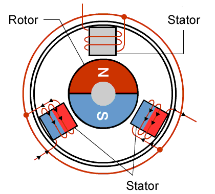
The stator is the stationary part of a brushless DC motor and is responsible for creating the magnetic field that drives the rotor. It consists of multiple copper windings mounted around a laminated steel core. These windings are connected to an Electronic Speed Controller (ESC), which supplies current to each phase in a specific sequence.
As the controller switches current between the windings, the magnetic field inside the motor continuously changes position, creating what is known as a rotating magnetic field. The permanent magnets on the rotor naturally follow this moving field, producing torque and causing the motor to rotate.
The design of the stator has a direct impact on motor performance. Factors such as winding configuration, slot design, and the number of poles can influence efficiency, torque output, operating temperature, and noise levels. For this reason, the stator is often considered one of the most critical components in a BLDC motor.
Rotor:
The rotor of a brushless DC motor is made up of permanent magnets that create a magnetic field. During operation, this magnetic field interacts with the rotating magnetic field generated by the stator, producing the torque that drives the motor.
Unlike the stator, the rotor does not require windings or a direct electrical connection. This simpler structure eliminates the need for brushes and commutators, reducing mechanical wear and improving reliability.
The rotor is designed with a specific number of magnetic poles, typically ranging from 2 to 8 depending on the application. Pole count plays an important role in motor performance. Motors with more poles generally deliver higher torque and smoother operation at lower speeds, while motors with fewer poles are better suited for high-speed applications. Selecting the right pole count is therefore a key part of motor design, as it directly affects the balance between torque, speed, and overall efficiency.
permanent magnets:
Permanent magnets generate the magnetic field that interacts with the stator to produce rotation. Most BLDC motors use neodymium iron boron (NdFeB) magnets because they provide a strong magnetic field while remaining compact and lightweight. In applications that involve high temperatures or harsh operating environments, samarium cobalt (SmCo) magnets may be used due to their superior thermal stability and corrosion resistance.The magnets are securely mounted to the rotor to ensure stable operation at high speeds.
Magnet design plays a major role in determining motor performance. Factors such as pole count, magnet placement, and magnetic strength all influence torque output, speed capability, and overall efficiency. By optimizing these parameters, motor designers can tailor a BLDC motor to meet the specific requirements of different applications, whether the priority is high torque, high speed, or maximum energy efficiency.
Types of BLDC Motors
Inner-Rotor BLDC Motors
In an inner-rotor brushless DC motor, the permanent magnet rotor is located at the center of the motor, spinning inside the stationary stator windings. This is the more widely used configuration across industrial and commercial applications. Because the rotor occupies only the core of the motor cross-section, its diameter and mass are relatively small, resulting in low rotational inertia. Low inertia means the motor can accelerate and decelerate rapidly, which is essential in servo drives, robotic joints, and precision-positioning systems where dynamic response is a critical design requirement.
The compact rotor also allows inner-rotor motors to achieve high rotational speeds. Combined with a cylindrical housing that integrates naturally into standard machine assemblies, the inner-rotor design is well suited to power tools, pumps, compressors, cooling fans, and industrial drive applications where a high-speed, compact motor with fast dynamic response is required. Heat generated in the stator windings can be conducted directly through the motor housing to the surrounding structure, which simplifies thermal management in continuous-duty operation.
Outer-Rotor BLDC Motors
In an outer-rotor brushless DC motor, the rotor forms a cylindrical shell or cup that surrounds the stator and rotates around it. The permanent magnets are mounted on the inner surface of this outer rotor shell, facing inward toward the stator windings at the motor's center. This inverted arrangement places the magnetic air gap at a larger radius, which increases the effective torque arm and allows more magnetic poles to be accommodated around the rotor circumference.
The result is a motor that generates substantially higher torque at lower rotational speeds compared with an inner-rotor design of equivalent size and power. Outer-rotor motors are therefore the preferred choice for direct-drive applications where speed reduction gearing is undesirable — notably drone and UAV propulsion, direct-drive ceiling and axial fans, electric bicycle hub motors, and turntable or platter drives in precision instruments. The trade-off is a larger outer diameter and higher rotational inertia, which limits dynamic response relative to inner-rotor designs. Thermal management also requires more careful consideration, as the rotating outer shell restricts airflow around the stator.
How does a BLDC motor Rotate?
The operation of a brushless DC motor is based on the interaction between the magnetic field generated by the stator and the permanent magnets mounted on the rotor.
When current is supplied to a stator winding, it creates a magnetic field that attracts and repels the rotor magnets. This magnetic force generates torque and causes the rotor to move. However, if the same winding remained energized continuously, the rotor would simply align with the magnetic field and stop rotating.
To keep the motor running, the magnetic field inside the stator must continuously change position. This is achieved through a process known as electronic commutation. Instead of using brushes and a mechanical commutator like a traditional DC motor, a BLDC motor relies on an electronic controller to switch current between different stator windings at precisely timed intervals.
The controller determines the rotor position using Hall-effect sensors or sensorless back-EMF detection. Based on this information, it energizes the appropriate winding sequence, creating a rotating magnetic field that continuously pulls the rotor forward.
The controller is mainly composed of three core parts: position feedback devices (such as Hall sensors or back-EMF detection circuits), a microcontroller or digital signal processor that runs intelligent control algorithms, and power electronic components like transistors and MOSFETs for switching current paths. These modules cooperate to realize electronic commutation and manage the energization of each motor phase. The controller first identifies rotor position via position feedback devices. Based on this positional data, it energizes windings in the correct sequence to form a rotating magnetic field that continuously pulls the rotor forward, maintaining a stable rotating magnetic field for smooth operation, efficient torque output and precise speed control.
Advantages of BLDC Motors
High Efficiency
BLDC motors are highly efficient because they eliminate brush friction and commutator losses. Combined with high-performance permanent magnets, they convert more electrical energy into useful mechanical output while generating less heat.
Long Service Life
Without brushes or commutators, there are fewer wear components inside a BLDC motor. This significantly reduces maintenance requirements and helps extend operating life.
High Power Density
BLDC motors can deliver high torque and power from a compact package. Their lightweight rotor design also improves dynamic response and acceleration performance.
Low Electrical Noise
Since there is no brush-to-commutator contact, BLDC motors produce far less electrical noise and electromagnetic interference(EMI) than traditional brushed motors.
Precise Control
When paired with an electronic controller, BLDC motors provide accurate speed and torque control across a wide operating range, making them ideal for automation and precision applications.
Ideal Applications forBLDC Motors
BLDC motors are widely used in industries where efficiency, reliability, and precise control are essential. Typical applications include industrial automation systems, robotics, CNC equipment, power tools, medical devices, and electric vehicles. Their ability to deliver high torque, fast response, and long service life makes them well suited for demanding operating environments.
Hongyang Motor provides customized motor solutions for a wide range of industrial and commercial applications. Our engineering team works closely with customers to help select the most suitable motor technology based on performance requirements, operating conditions, and cost targets. In addition, we are actively developing a range of brushless DC motor solutions to meet the growing demand for higher efficiency, longer service life, and advanced motion-control performance across various industries..
News
-
Brush DC Motor Origins and Physical Foundations The Brush DC Motor is a pioneer in converting electrical energy into mechanical motion, and its history is closely intertwined with ...
READ MORE -
Who Is Still Using Brushed DC Motors These Days? Brushed DC motors in small appliances Despite the growing adoption of brushless motor technology, small appliances remain a major c...
READ MORE -
Brush DC Motor Applications in Consumer Electronics and Smart Devices Brush DC Motor Role in Consumer Electronics Design Brush DC Motor plays a critical role in the design and func...
READ MORE

Quick Links
 Home
Home


Copyright © Yuyao Hongyang Micromotor Co., Ltd. All rights reserved.

