

 Eng
Eng 
 русский
 Español

 Home / News / Industry News / Gear Motor vs. Stepper Motor: Differences, Selection Guide, and Small Gear Motor Specs
 Gear Motor vs. Stepper Motor: Differences, Selection Guide, and Small Gear Motor Specs
 2026.07.22
 Industry News
In a gear motor vs stepper motor comparison, the short answer is: choose a gear motor when you need high, steady torque at low speed for continuous rotation, and choose a stepper motor when you need precise, repeatable positioning. A gear motor pairs a standard motor with a gearbox that mechanically multiplies torque and reduces output speed, while a stepper motor moves in fixed, discrete angular increments controlled directly by electrical pulses — no gearbox required, though one can still be added for extra torque. A small gear motor applies the same torque-multiplying principle at miniature scale, commonly 6mm to 42mm in diameter, for compact devices like door locks, camera gimbals, and robotics. Below, we break down how each motor type actually works, compare their real performance trade-offs, and cover what to look for when specifying a small gear motor.
How a Gear Motor Works
A gear motor is a standard AC or DC motor combined with a gearbox, or gear reduction system, attached directly to its output shaft. The gearbox acts as a torque multiplier: a small, efficient motor spins fast but weakly, and the gears trade that speed for force, letting the final output shaft turn slower while pushing or pulling with significantly more torque.
This design makes gear motors the default choice for applications needing sustained rotational force rather than precise stopping points — conveyor belts, elevators, electric vehicle drivetrains, and general industrial machinery all rely on this torque-for-speed trade.
Common gearbox types used in gear motors include:
- Spur gearboxes — simple, efficient, and cost-effective for moderate torque and speed needs
- Helical gearboxes — angled teeth produce smoother, quieter operation under higher loads
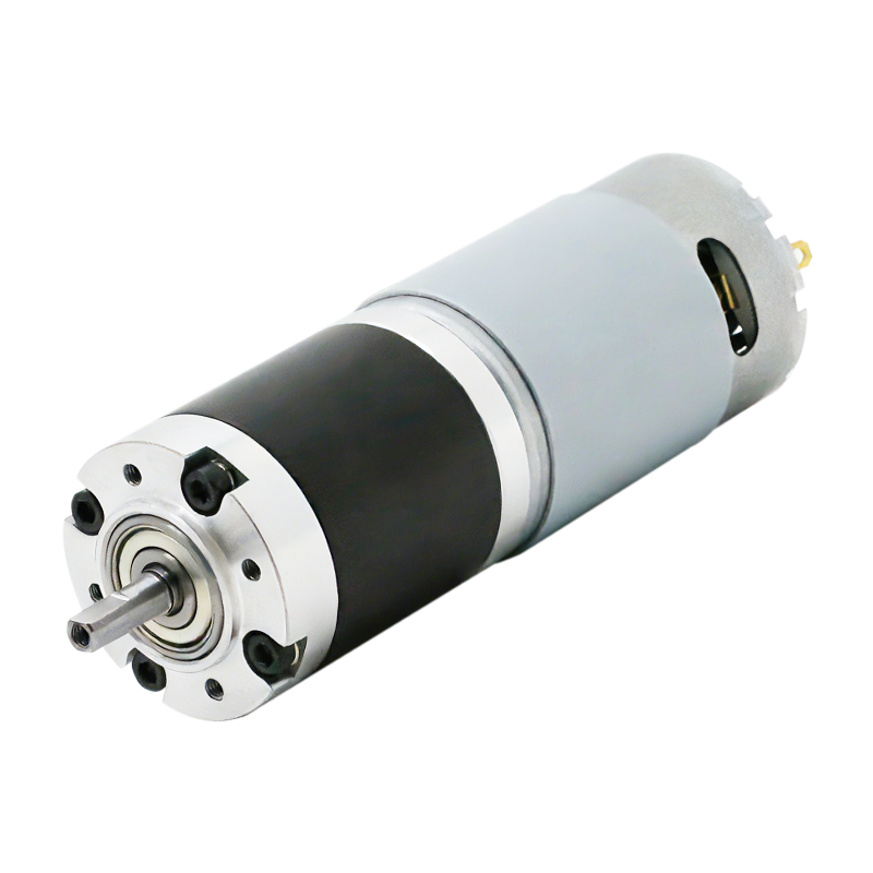
- Planetary gearboxes — highly compact with excellent torque density, common where space is limited
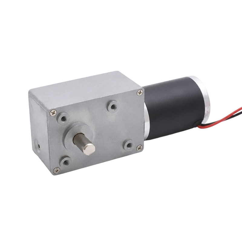
- Worm gearboxes — deliver very high reduction ratios and are non-back-drivable, which provides a natural holding or braking effect
How a Stepper Motor Works
A stepper motor is a type of motor that divides one full rotation into a fixed number of equal steps, moving its shaft in discrete, precise angular increments rather than spinning continuously and smoothly. A standard 1.8-degree stepper motor completes 200 full steps per revolution, and with microstepping — electronically subdividing each step — that resolution can be refined even further.
Because position is controlled directly by counting electrical pulses, stepper motors can achieve accurate positioning in an open-loop system, meaning they don't necessarily require an encoder or feedback sensor to know where the shaft is pointed. This is a major reason they're standard in equipment like 3D printers, CNC machines, and automated dispensers, where exact, repeatable movement matters more than raw rotational force.
Stepper motors also deliver strong holding torque at a standstill, keeping a shaft locked in position under load without drifting — useful for applications like robotic arm joints that need to stay put between movements.
Gear Motor vs Stepper Motor: Direct Comparison
The table below lines up the practical differences that typically decide which motor type fits a given design.
| Factor | Gear Motor | Stepper Motor |
|---|---|---|
| Primary strength | High, consistent torque | Precise, repeatable positioning |
| Motion type | Continuous rotation | Discrete, fixed-angle steps |
| Torque across speed range | Consistent | High at low speed, drops sharply as speed increases |
| Position feedback needed | Typically yes, for precise control | No — open-loop positioning by pulse count |
| Efficiency at high load | Reduced roughly 5–20% by gear friction | Can drop below 50% when pushed hard |
| Upfront cost | Higher, due to gearbox | Moderate |
Gear motors also introduce a mechanical quirk worth knowing before you specify one: gear backlash — the small amount of play between meshing gear teeth — typically runs 0.5 to 3 degrees, which can translate into a slight loss of precision in position-sensitive applications. A stepper motor's direct-drive design avoids this issue entirely, which is part of why it dominates in positioning-critical equipment.
When to Choose Each Motor Type
Matching the motor to the job usually comes down to answering one question: does the application need to move something with force, or place something exactly?
Choose a gear motor when
- The application needs high torque at low, continuous speed — conveyors, elevators, and heavy machinery
- The load is substantial and exact stopping position matters less than raw pulling or pushing force
- The mechanism runs continuously rather than starting and stopping in discrete increments
Choose a stepper motor when
- Exact, repeatable positioning is the priority — 3D printers, CNC cutting heads, and camera focus mechanisms
- The design benefits from open-loop control, avoiding the added cost and complexity of an encoder
- A shaft needs to hold a fixed position under load without drifting between movements
Some designs use a geared stepper motor to get the best of both worlds — the gearbox multiplies the stepper's native torque while also refining its effective step resolution, since each motor step now corresponds to a smaller angle at the output shaft after the gear reduction.
What Defines a Small Gear Motor
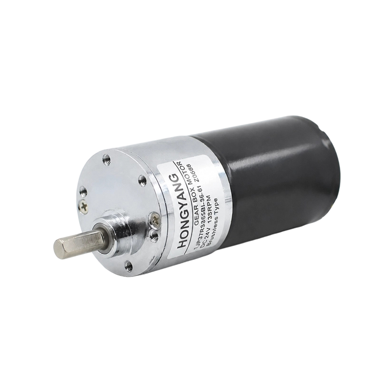
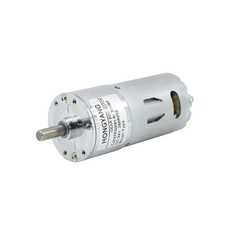
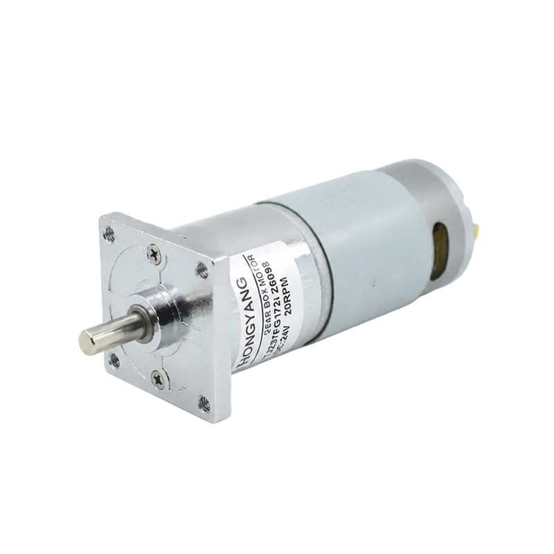
A small gear motor applies the same motor-plus-gearbox principle at a miniature scale, built for applications where both torque and physical footprint matter. Manufacturers commonly offer small gear motors ranging from about 6mm to 42mm in outer diameter, with rated voltages typically spanning 2V to 24V DC and output speeds anywhere from roughly 5 RPM up to 2,000 RPM depending on the gear ratio selected.
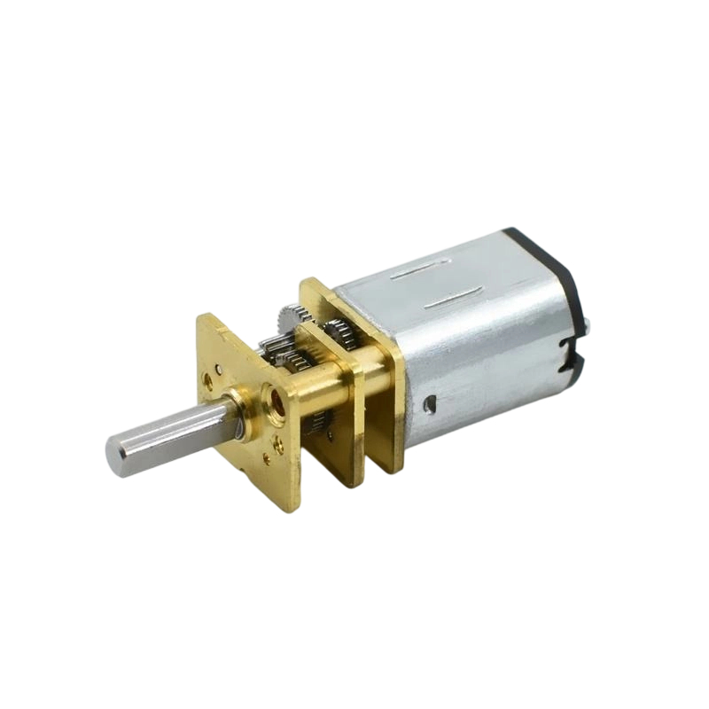
At the smallest end of that range, a 6mm gear motor can weigh just over a gram — light enough for miniature robotics, camera gimbals, or automated door locks — while still multiplying torque well beyond what the bare motor could deliver alone. A representative micro planetary unit, for example, combines an 8-10mm motor with a roughly 10mm gearbox to produce a 1:171 reduction ratio, useful where a very slow, high-torque output is needed from a tiny package.
Choosing Gearbox Material and Ratio for a Small Gear Motor
Two specification choices matter most once you've settled on a small gear motor: what the gears are made from, and how aggressive the reduction ratio is.
- Plastic gears are lighter, quieter, and more cost-effective — a good fit for consumer electronics, toys, and light-duty mechanisms with limited duty cycles.
- Metal gears transfer larger forces and last significantly longer under the same load — commonly two to three times the service life of an equivalent plastic gearbox — making them the better choice for demanding or continuous-use applications.
- Mixed metal-and-plastic gearboxes offer a middle ground, often using plastic on the fast-spinning input stage to reduce noise while keeping metal on the higher-torque output stages.
- Higher gear ratios trade maximum speed for greater torque multiplication — a 1:171 ratio produces far more output torque than a 1:27 ratio from the same base motor, but spins the output shaft much more slowly.
When specifying a small gear motor for a new design, it's worth sharing the target load, duty cycle, and noise tolerance with the manufacturer directly — gear ratio, gearbox material, output shaft style, and voltage are all commonly customizable even at these small diameters, so a stock part rarely needs to be the final compromise.
News
-
Brush DC Motor Origins and Physical Foundations The Brush DC Motor is a pioneer in converting electrical energy into mechanical motion, and its history is closely intertwined with ...
READ MORE -
Who Is Still Using Brushed DC Motors These Days? Brushed DC motors in small appliances Despite the growing adoption of brushless motor technology, small appliances remain a major c...
READ MORE -
Brush DC Motor Applications in Consumer Electronics and Smart Devices Brush DC Motor Role in Consumer Electronics Design Brush DC Motor plays a critical role in the design and func...
READ MORE

Quick Links
 Home
Home


Copyright © Yuyao Hongyang Micromotor Co., Ltd. All rights reserved.

