

 Eng
Eng 
 русский
 Español


Application of Varistors in Micro DC Motors
 2026.07.14
 Industry News
A varistor is a nonlinear voltage-limiting protection component designed to absorb circuit overvoltage surges and protect precision downstream electronic components. Widely applied in brushed micro motors, it effectively solves common motor operating problems such as commutation voltage spikes, electromagnetic interference and brush wear.
This article systematically introduces the working principle of varistors, analyzes their core protective functions in micro motor operation, and provides standardized and practical component selection guidelines. It serves as a professional technical reference for hardware engineers, design developers and procurement personnel.
Operating Principle of Varistors
A voltage-dependent resistor (varistor) is highly sensitive to voltage changes. Its resistance remains at the megaohm level under normal low-voltage operating conditions and drops sharply to the milliohm level instantly when overvoltage surges occur, forming a low-impedance path to rapidly discharge surge current and realize voltage clamping protection.
1.1 Three Characteristic Operating Zones
The working state of a varistor can be divided into three distinct regions according to the applied voltage:
1) Leakage Region
When the applied voltage is within the normal working range of the circuit, the varistor presents extremely high resistance with only tiny leakage current passing through. It does not affect the normal operation of the circuit and remains in a long-term standby protection state.
2) Nonlinear Clamping Region
When transient surges or voltage spikes appear in the circuit, the varistor enters the nonlinear working region. The current increases sharply while the terminal voltage is stably clamped within a safe narrow range. This is the core working region for the varistor to absorb surges and suppress spikes, and it undertakes the main protection work in micro motor circuits.
3) Saturation Region
If the overvoltage continues to rise beyond the bearing range, the varistor enters the saturation region and behaves as a low-resistance linear component, resulting in a sharp increase in loop current. Long-term operation in this region will cause component overheating, burnout and even ceramic cracking. Therefore, saturation region operation is strictly prohibited in practical applications.
1.2 Material Conduction Mechanism
Common metal oxide varistors are sintered polycrystalline semiconductor ceramics, mainly made of zinc oxide (ZnO) with a small amount of auxiliary metal oxide additives such as bismuth oxide and cobalt oxide.
Each zinc oxide grain is wrapped by a high-resistance grain boundary layer. Under rated working voltage, the grain boundary blocks current conduction to ensure normal circuit operation. When the voltage exceeds the threshold value, Zener breakdown and tunneling effects occur at the grain boundary, the component resistance drops abruptly, and a high-speed discharge channel is formed to release surge energy instantly.
Core Functions of Varistors in Micro Motors
Most mainstream micro motors are brushed DC motors. During operation, carbon brushes and commutators continuously switch the current direction of armature windings. As the armature winding has inductive characteristics, it will store magnetic energy when energized. The instantaneous switching of current during commutation releases massive magnetic energy, forming high-voltage transient spikes, namely back electromotive force (Back EMF).
Without effective protection, commutation spikes will cause three major problems:
1) Accelerated Motor Wear
High-voltage spikes produce commutation sparks, causing high-temperature erosion on commutator segments and carbon brushes, aggravating mechanical wear and greatly shortening the overall service life of micro motors.
2) Severe Electromagnetic Interference
Commutation sparks radiate continuous electromagnetic noise, interfering with the normal operation of surrounding precision devices such as sensors, Bluetooth modules and control chips, leading to product EMC compliance failure.
3) Circuit Component Damage
Unsuppressed overvoltage spikes will be transmitted to the control PCB, easily breaking down drive ICs, capacitors and other precision components, increasing product failure rate and after-sales cost.
By connecting a varistor in parallel at the micro motor terminals, the component will instantly enter the nonlinear clamping region once commutation voltage spikes occur. It provides a low-impedance surge discharge path to clamp the overvoltage within a safe range, realizing three core protection effects:
- Effectively suppress commutation sparks and reduce wear of commutators and carbon brushes;
- Significantly reduce electromagnetic radiation interference to meet industrial EMI certification standards;
- Absorb transient surge energy to protect backend circuit precision components.
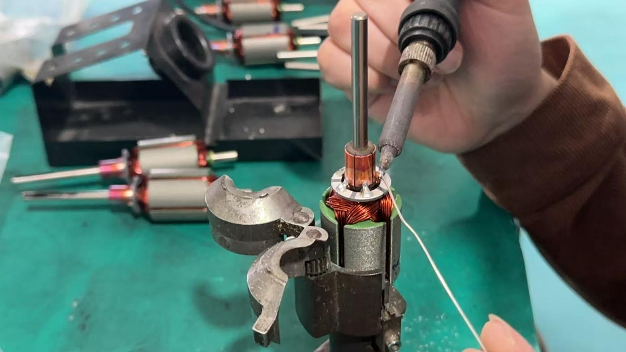
Professional Varistor Selection Guide for Micro Motors
The selection of micro motor dedicated varistors focuses on two core parameters: varistor voltage (V₁mA) and surge current capacity.
Key Parameter 1: Varistor Voltage (V₁mA)
Varistor voltage (V₁mA), also known as threshold breakdown voltage, refers to the voltage across the component when a 1mA DC current passes through the varistor. It is the most critical parameter affecting protection accuracy and service life.
DC Micro Motor Selection Formula
V₁mA = (1.8 ~ 2.2) × Motor Rated DC Supply Voltage (Vp)
Two Basic Selection Constraints
- The varistor voltage must be higher than the maximum continuous working voltage of the system to avoid false triggering and abnormal heating;
- The varistor voltage must be lower than the maximum withstand voltage of protected components to ensure effective clamping before circuit damage occurs.
Practical Application Example
For a 12V rated DC micro motor:
Minimum selection value: 12V × 1.8 = 21.6V
Maximum selection value: 12V × 2.2 = 26.4V
Recommended mainstream specifications: 24V / 26V varistors.
Key Parameter 2: Surge Current Capacity
Surge current capacity refers to the maximum peak pulse current that a varistor can withstand under standard test conditions (25℃ ambient temperature, specified surge waveform and impact times), with the varistor voltage change controlled within ±10%.
Selection Principles
- A higher surge current rating provides stronger anti-interference capability and more stable protection performance;
- The actual surge current generated by the motor must be lower than the component’s rated maximum surge current to ensure long-term reliable operation;
- For scenarios where surge current cannot be accurately calculated, select specifications based on motor power, start-stop frequency and actual load conditions.
Conclusion
As a low-cost, high-reliability and high-efficiency voltage protection component, varistors play an irreplaceable role in brushed micro motor systems. By absorbing Back EMF generated during motor commutation, they effectively suppress spark wear, reduce electromagnetic interference, protect precision circuit components, and significantly improve the overall stability and service life of micro motor equipment.
Reasonable parameter selection is the key to giving full play to varistor protection performance. If you have DC motor requirements, please contact us for customized solution support.
News
-
Brush DC Motor Origins and Physical Foundations The Brush DC Motor is a pioneer in converting electrical energy into mechanical motion, and its history is closely intertwined with ...
READ MORE -
Who Is Still Using Brushed DC Motors These Days? Brushed DC motors in small appliances Despite the growing adoption of brushless motor technology, small appliances remain a major c...
READ MORE -
Brush DC Motor Applications in Consumer Electronics and Smart Devices Brush DC Motor Role in Consumer Electronics Design Brush DC Motor plays a critical role in the design and func...
READ MORE

Quick Links
 Home
Home


Copyright © Yuyao Hongyang Micromotor Co., Ltd. All rights reserved.

