

 Eng

 русский
 Español


 Home / News / Industry News / How to Choose the Right Brushless Motor for Your Product: A Practical Selection Guide
How to Choose the Right Brushless Motor for Your Product: A Practical Selection Guide
 2026.11.19
 Industry News
Choosing a brushless motor is rarely about finding the biggest or the fastest unit on a datasheet. In most product projects it is a balancing act: enough torque to start the load, enough headroom to survive the worst case, an efficiency level that keeps heat under control, and a cost that still makes sense at the volume you plan to build. Having supplied micro DC motors to equipment makers for more than three decades, we have seen designs succeed or stall for the same handful of reasons, and most of them had nothing to do with the motor alone.
This guide walks through the questions we usually ask a customer before quoting a brushless motor: what the load actually needs, how the numbers on a datasheet translate into behavior, and where a small change in specification saves weeks of rework later. If you only have a rough idea of your application today, that is a perfectly normal starting point.
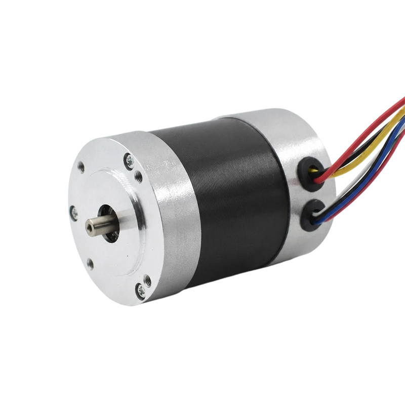
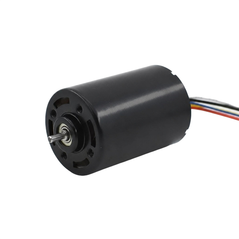
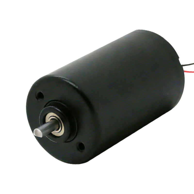 Brushless DC Motor Range with Customizable SpecificationsBrowse inner-rotor, outer-rotor, and coreless BLDC options with customizable speed, torque, and power for application load calculations.View Product →
Begin With the Load, Not the Motor
Start by describing what the motor has to move. Torque at the shaft comes from three places: friction in the mechanism, the force needed to accelerate the mass, and any continuous load such as a pump impeller, a fan blade or gravity on a lifting axis. Write each of them down separately, because they behave differently. Acceleration torque is short and often large, while friction torque is small but runs for hours.
Then decide whether those loads are continuous or intermittent. A motor sized for peak acceleration will run cold most of the day; a motor sized only for average load may stall on the first cold morning. It also helps to know the worst-case ambient temperature, because an enclosure that reaches 60 °C changes the thermal budget dramatically.
If the required speed is low and the torque is high, a gearbox is often the cheaper and more compact answer than a larger direct-drive motor, since the gear stage multiplies torque while reducing speed. Our gear motor range is built exactly for that combination.
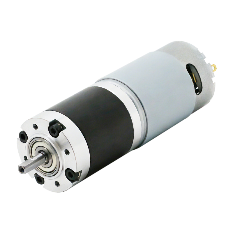 Gear Motor Range for Low-Speed, High-Torque DrivesCompare planetary, N20, 37 mm, and worm gear motors with selectable ratios, shafts, speed, torque, and gear materials for reduced-speed drive designs.View Product →
Translate the Application Into Motor Numbers
Once the load is understood, convert it into a target operating point. Mechanical power is torque multiplied by angular speed, so a mechanism that needs 0.2 N·m at 3000 rpm is asking for roughly 63 W at the shaft. From there, a realistic efficiency assumption, usually 75 to 85 percent for a small brushless motor with its driver, gives the electrical input you should plan for.
Two constants do most of the work here. The torque constant tells you how many amps you need per newton-metre of torque, and the speed constant tells you how fast the motor turns per volt applied. Multiply the required torque by the current draw and you have a first estimate of copper loss; compare that with the rated continuous current on the datasheet and you quickly see whether the motor is working comfortably or living on the edge.
Voltage, Speed and Winding Choices
The supply you already have, whether a 12 V battery pack, a 24 V rail or a rectified mains stage, narrows the winding options more than any other decision. A low-voltage supply needs a low-resistance, high-current winding to reach the target speed, while a higher bus voltage reaches the same speed with lower current and therefore lower I²R loss. The trade-off shows up in cable size, connector rating and driver cost rather than in the motor alone.
Keep in mind that the motor only ever reaches a fraction of its no-load speed under load, and that controllers limit duty cycle as the bus voltage sags. Leaving 20 to 30 percent speed headroom above your maximum requirement is usually a sensible cushion, especially in battery-powered products where the pack voltage falls as it discharges.
Sensored or Sensorless: Match the Control Strategy
Sensorless control keeps the motor and cable simple and costs less, but it relies on back-EMF information, which is unavailable at standstill. Applications that start against a heavy load, such as a pump with a filled chamber or a mechanism resting on a stop, may need a sensor to guarantee reliable startup and smooth low-speed torque.
Hall sensors add three wires and a small cost per unit, yet they make field-oriented control straightforward and give repeatable behavior across production batches. Encoders go further and enable position or speed loops. The right answer depends on how much startup torque you need, how quietly the product must run, and how much the controller budget can absorb.
Reading a Brushless Motor Datasheet
Datasheets are written for comparison, not for storytelling, so knowing which line answers which question saves a lot of time.
| Specification | What it tells you | Where it matters most |
|---|---|---|
| Rated voltage | The bus voltage the winding is designed around | Battery packs and adapter-driven products |
| Speed constant or no-load speed | How fast the shaft turns per volt, or free-running RPM | First estimate of achievable top speed |
| Rated torque and current | The continuous operating point the motor can hold | Sizing against the real, measured load |
| Torque constant | Torque produced per amp of current | Driver rating and current draw from the supply |
| Winding resistance | Copper loss at a given current | Heat rise inside sealed or fanless housings |
| Sensor type | Hall, encoder or sensorless commutation | Startup behavior and controller cost |
Efficiency, Heat and Duty Cycle
Efficiency figures are only meaningful at a stated operating point. A motor that is 85 percent efficient at its rated load may be 60 percent efficient at half that torque, because iron and friction losses stay roughly constant while copper loss falls with the square of current. Ask for a curve rather than a single number, and check where your real operating point sits on it.
Thermal behavior decides long-term reliability more than any single electrical parameter. Enclosed housings, high ambient temperatures and continuous duty all reduce the usable current, while intermittent duty leaves room to push harder for short bursts. Insulation class and bearing lubricant ratings set the ceiling on how hot the motor can safely run.
Mechanical Fit, Noise and Lifetime
Frame size, shaft diameter, mounting pattern and overall length usually constrain the design before the electrical specification does. Confirm the shaft length, the allowed radial and axial loads, and whether the bearing arrangement suits a belt, a screw or a direct coupling. A well-chosen motor with the wrong bearing preload will still fail early.
Acoustic performance follows from cogging torque, rotor balance and commutation quality. For products used close to people, such as appliances, office equipment or medical devices, it is worth specifying noise at the actual mounting condition rather than trusting a free-field measurement on a test bench.
Where the Trade-offs Change
Not every application rewards the same priorities. A drone propulsion motor is designed around thrust per watt and low weight, so thin magnet wire, high pole counts and lightweight housings dominate the design. By contrast, an industrial robots axis values repeatability, holding torque and long service life far above weight. A robot vacuum sits somewhere in between, needing quiet operation, compact size and a predictable lifetime at high production volume.
Our drone propulsion motor is a good example of how a single application can push a specification in one clear direction.
Where Experience Saves Iterations
Most selection problems are solved fastest with a sample on a bench. Since 1988 we have built micro DC motors in Yuyao, working from customer drawings and application descriptions rather than from catalogue numbers alone. Custom windings, shaft and cable configurations, and connector options can be evaluated on prototype units before a production tool is committed, and our testing laboratory is used to check torque, current and temperature behavior against the intended duty cycle.
Facilities and products are manufactured to ISO 9001, RoHS and REACH requirements, with annual capacity above ten million units for customers who move from prototype to series production. For buyers comparing suppliers, the useful questions are the same ones you would ask internally: what is measured on each batch, what happens when a parameter drifts, and how quickly a modified sample can be delivered.
A Selection Checklist
- Measure or calculate the continuous and peak torque at the shaft.
- Define the speed range, including the slowest useful speed.
- Confirm the available supply voltage and its tolerance.
- Estimate current draw from the torque constant and check the driver rating.
- Decide whether startup conditions require Hall sensors or an encoder.
- Check the thermal path, ambient temperature and duty cycle.
- Verify shaft, mounting, bearing loads and acoustic targets.
- Test a sample at the real operating point before releasing tooling.
Selection becomes much simpler once the load, the supply and the control strategy are written down in numbers. From there, a brushless motor is no longer a black box with a long datasheet, but a component you can compare against alternatives on the few parameters that actually shape your product. If a specification is still unclear, sending us the application details is usually the fastest way to narrow the options.
News
-
Brush DC Motor Origins and Physical Foundations The Brush DC Motor is a pioneer in converting electrical energy into mechanical motion, and its history is closely intertwined with ...
READ MORE -
Who Is Still Using Brushed DC Motors These Days? Brushed DC motors in small appliances Despite the growing adoption of brushless motor technology, small appliances remain a major c...
READ MORE -
Brush DC Motor Applications in Consumer Electronics and Smart Devices Brush DC Motor Role in Consumer Electronics Design Brush DC Motor plays a critical role in the design and func...
READ MORE

Quick Links
 Home


Copyright © Yuyao Hongyang Micromotor Co., Ltd. All rights reserved.

