

 Eng

 русский
 Español


 Home / News / Industry News / How Does PWM Control Motor Speed? A Practical Guide for DC Motor Users
How Does PWM Control Motor Speed? A Practical Guide for DC Motor Users
 2026.11.02
 Industry News
Speed control is often the first question engineers ask when they start working with a small DC motor. The answer, in most modern designs, is pulse width modulation, or PWM for short. Rather than lowering the supply voltage with a resistor and letting the extra energy escape as heat, PWM switches the motor's power on and off very rapidly. From the motor's point of view, this chopped waveform acts like a lower average voltage, and the rotor speed settles to a value that matches that average. It is simple, efficient, and easy to generate with a microcontroller or a small driver IC.
What Is Pulse Width Modulation?
Pulse width modulation is a method of controlling the average power delivered to an electrical load by turning a steady DC signal on and off at a fixed rate. Two numbers define the signal: the duty cycle and the switching frequency.
Duty Cycle
The duty cycle is the percentage of time the signal stays on during one switching period. A 100% duty cycle connects the motor to the full supply voltage without interruption; a 0% duty cycle leaves it completely off. A 50% duty cycle keeps the motor energised for half of each period, which gives roughly half the average voltage. Because a motor's mechanical time constant is much longer than a typical PWM period, the rotor does not follow individual pulses. Instead, it responds to the average value, and that is exactly what makes PWM such a clean speed-control tool.
Switching Frequency
The switching frequency is how many times per second the signal cycles on and off. Typical values for small DC motors range from a few hundred hertz to tens of kilohertz. Higher frequencies reduce current ripple in the winding, while lower frequencies keep switching losses in the driver smaller. Choosing the right frequency is a balance between electrical noise, acoustic noise and efficiency, which we will return to later.
How PWM Controls Motor Speed
When a PWM signal drives a DC motor, current flows only during the on time of each pulse. The average voltage across the motor terminals equals the supply voltage multiplied by the duty cycle. The no-load speed of a DC motor is approximately proportional to that average voltage, so increasing the duty cycle raises the speed and decreasing it lowers the speed. Under load, the same relationship holds, although the torque produced by the motor also depends on the average current.
The current and torque behave in a similar way to the voltage. During the on phase, current builds up in the winding; during the off phase, it freewheels through the driver or a flyback diode. The average current determines the torque available at the shaft. This means PWM not only adjusts speed, but also maintains smooth running at low speeds with repeatable torque — useful in fans, pumps and small household appliances where a simple and reliable control method is preferred.
For a practical example, consider a 12 V brushed DC motor with a no-load speed of 4000 rpm. The table below shows how the duty cycle maps to average voltage and approximate speed.
| Duty Cycle | Average Voltage | Approx. No-Load Speed | What You Would Notice |
|---|---|---|---|
| 100% | 12.0 V | 4000 rpm | Full speed, maximum airflow |
| 75% | 9.0 V | 3000 rpm | Clearly slower, still strong |
| 50% | 6.0 V | 2000 rpm | Moderate speed, quiet |
| 25% | 3.0 V | 1000 rpm | Slow and gentle |
| 0% | 0 V | 0 rpm | Motor stopped |
Brushed or Brushless – PWM Works for Both
PWM is equally important for brushed and brushless DC motors, although the implementation looks different.
Brushed DC Motors
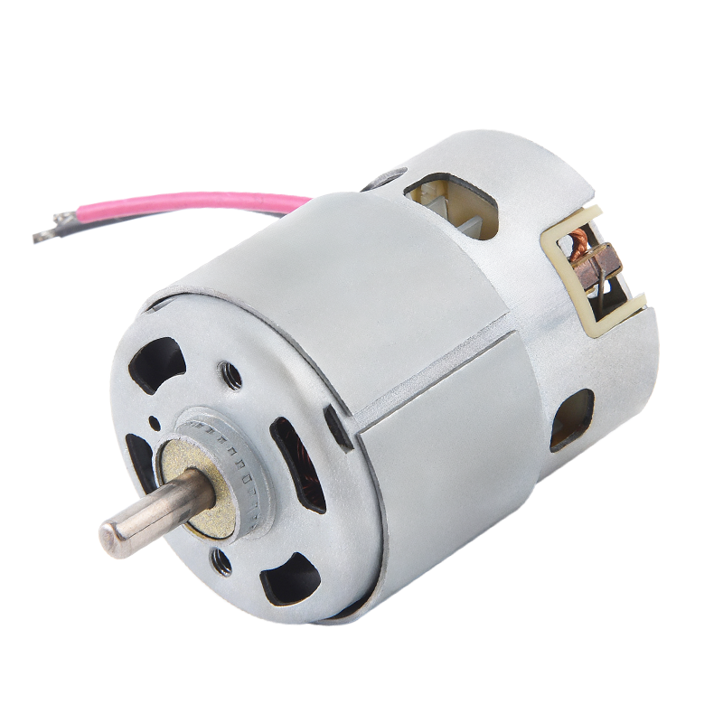
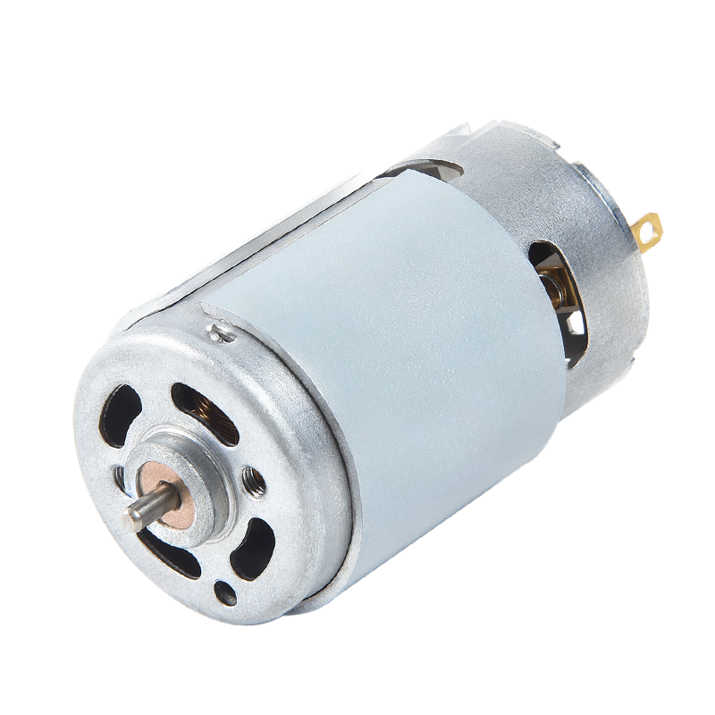
For a brushed motor, PWM is usually applied directly to the motor terminals through a transistor or an H-bridge. The brushes and commutator handle the reversal of current, so the control scheme stays simple. Many of our brushed motors, such as the RS360 used in fans, accept PWM drive directly and respond linearly across a wide range of duty cycles. If you want predictable speed control with minimal electronics, a brushed motor is often the most cost-effective starting point.
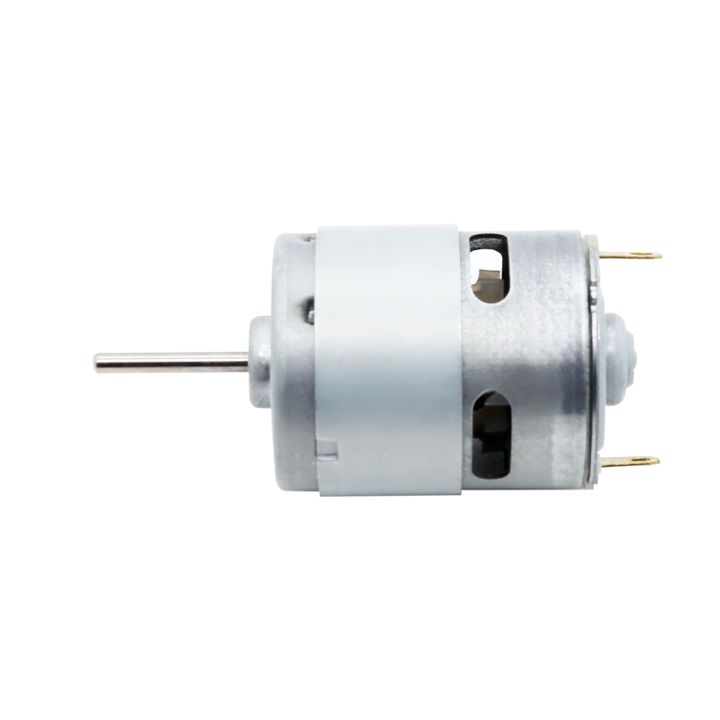 RS-360 Brushed DC Motor for Air PumpsCompact high-speed brushed motor suited for fans and pumps, offering linear PWM response and cost-effective control. Available in RS-365 variant with customizable specifications.View Product →
Brushless DC Motors
In a brushless motor, an electronic speed controller takes over commutation. The controller energises the windings in sequence and uses PWM to regulate the average voltage applied to each phase. This is the standard method in drones, cooling fans and precision equipment. Because there are no brushes to wear out, a brushless motor with PWM control delivers long life and consistent performance. Our brushless DC motor for drones is a typical example of a design where the electronic speed controller and PWM work together to translate a throttle command into smooth, responsive speed changes.
Choosing the Right PWM Frequency
The switching frequency has a direct effect on noise, efficiency and current quality, so it deserves careful attention.
Audible Noise
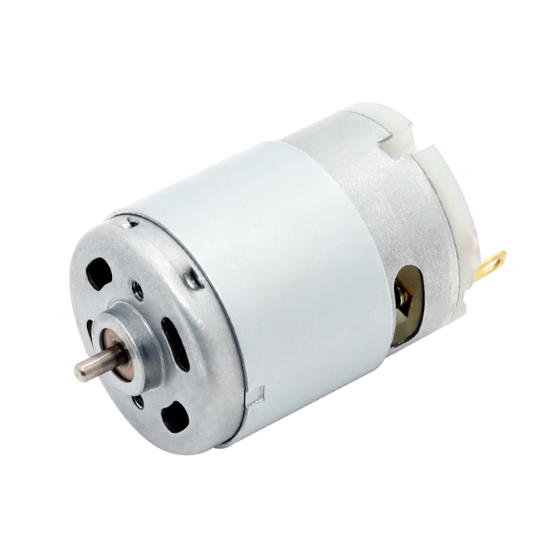
Frequencies in the 1 kHz to 5 kHz range often produce an audible whine from the motor windings. For appliances meant to run quietly in a home, designers usually select a frequency above 18 kHz, beyond the range of human hearing. Our RS380SL mute motor for home applications is a good example of a design that benefits from a high-frequency PWM drive; pairing a quiet-running motor with an inaudible switching frequency keeps the finished product unobtrusive.
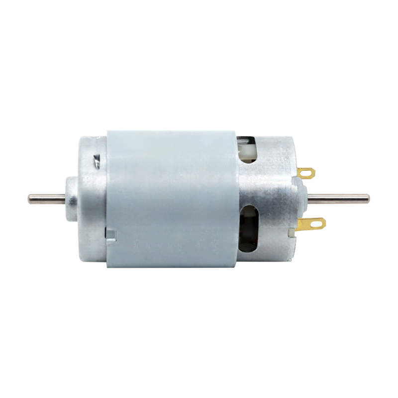 RS-380SL Quiet Brushed DC Motor for Home AppliancesExtended RS-380/385 model designed for quiet operation in coffee makers and similar devices. Benefits from high-frequency PWM drive to minimize audible whine and maintain smooth torque.View Product →
Current Ripple
Higher switching frequencies keep the winding current more constant, which reduces torque ripple and electromagnetic interference. However, every transition of the driver transistor dissipates a small amount of energy, so extremely high frequencies increase switching losses. The most efficient choice is often the lowest frequency that still keeps current ripple and acoustic noise at acceptable levels.
Motor Heating
PWM frequency also influences heating. Core losses in the motor rise as the frequency increases, especially if the motor is driven through long cables or a poorly laid-out driver. Keeping the driver close to the motor, using short leads and choosing a sensible frequency all help control the temperature rise.
Practical Advice for PWM Speed Control
- Choose a duty-cycle range that suits the application. Avoid the very low end if the motor needs enough torque to overcome static friction at start-up.
- Always fit a flyback diode across the motor to protect the driver from inductive spikes during the off phase.
- Test the frequency with the real motor and load. A frequency that works well for one motor may be audible or cause vibration with another.
- For products sold internationally, plan for electromagnetic compatibility. PWM drivers are a common source of both conducted and radiated emissions.
Why PWM Is the Preferred Method
From a manufacturing perspective, PWM speed control offers clear advantages. The driver transistor operates only in full saturation or full cut-off, so it dissipates very little power compared with a linear regulator. PWM signals are easy to generate with a microcontroller, which means no extra analog circuitry is needed. And because the speed is set by a digital signal, the behaviour is repeatable from unit to unit. These benefits explain why PWM appears in everything from electric toothbrushes to automotive actuators.
Conclusion
Understanding how PWM controls motor speed ultimately comes down to three ideas: the duty cycle sets the average voltage, the average voltage sets the speed, and the switching frequency determines how smoothly the current flows. Whether you are developing a cooling fan, a coffee machine, a garden tool or a medical device, PWM gives you a simple, efficient and flexible way to deliver the speed your users need. And when you start with a motor that has been designed and tested with PWM in mind, the rest of the development work becomes much easier. You can browse our application pages to see how PWM-controlled micro motors are used across different industries.
News
-
Brush DC Motor Origins and Physical Foundations The Brush DC Motor is a pioneer in converting electrical energy into mechanical motion, and its history is closely intertwined with ...
READ MORE -
Who Is Still Using Brushed DC Motors These Days? Brushed DC motors in small appliances Despite the growing adoption of brushless motor technology, small appliances remain a major c...
READ MORE -
Brush DC Motor Applications in Consumer Electronics and Smart Devices Brush DC Motor Role in Consumer Electronics Design Brush DC Motor plays a critical role in the design and func...
READ MORE

Quick Links
 Home


Copyright © Yuyao Hongyang Micromotor Co., Ltd. All rights reserved.

